

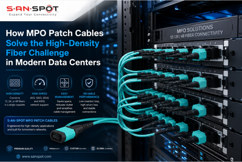
The High-Density Fiber Problem No One Talks About Enough
Data center capacity is growing faster than most cabling strategies can keep up with. According to IDC, global data center IP traffic will exceed 20 zettabytes annually by 2027. That growth puts immense pressure on physical infrastructure, especially fiber cabling. Traditional single-fiber connectors made sense when port counts were manageable. Today, they create a rat’s nest of individual cables that slows deployments, increases error rates, and exhausts available rack space.
Network engineers know the symptom well. You open a densely populated patch panel and find dozens of individual LC or SC connectors running in parallel. Tracing a single circuit takes longer than it should. Moves, adds, and changes turn into multi-hour events. Cooling airflow suffers because cable bundles block pathways. These are not minor inconveniences. They are operational risks that affect uptime and labor cost.
The root cause is simple. Single-fiber connectors were not designed for the port densities that 40G, 100G, and 400G architectures demand. A 40G parallel optic transceiver requires eight fibers. Using individual connectors for each of those fibers multiplies the problem by every port in the cabinet.
How an MPO Patch Cable Changes the Equation
An MPO patch cable, short for multi-fiber push-on, consolidates multiple fibers into a single connector interface. Standard configurations carry 12 or 24 fibers per connector. Some high-density variants support 48 or 72 fibers in a single plug. This consolidation is not just convenient. It is a structural rethinking of how fiber is routed and managed in high-port-count environments.
The International Electrotechnical Commission standard IEC 61754-7 governs MPO connector geometry and performance. Connectors must meet tight tolerances on ferrule alignment, fiber positioning, and end-face geometry. A properly manufactured MPO connector achieves insertion loss below 0.35 dB per mated pair. That performance level is sufficient for 40G SR4, 100G SR4, and even 400G SR8 optical transport.
Beyond raw density, the MPO patch cable offers significant deployment advantages. A single cable replaces twelve or twenty-four individual runs. Termination time drops proportionally. Cable management becomes straightforward because one routed cable serves an entire transceiver’s fiber requirement. Troubleshooting is faster because a single connector swap addresses all fibers serving a port.
Type-A and Type-B polarity conventions, defined by TIA-568, determine how fibers map through a connection. Choosing the wrong polarity for a given transceiver pairing is the most common commissioning error in MPO deployments. Type-A cables pass fibers straight through without inversion. Type-B cables invert the fiber order end-to-end. Getting this right before deployment prevents misconnection at scale.
Fiber Count and Application Matching
Matching the correct fiber count to the intended application is a prerequisite for reliable performance. The table below summarizes common pairings.
- 12-fiber MPO: Standard for 40G SR4, 100G SR4, and short-reach parallel optic applications
- 24-fiber MPO: Suited for 100G SR10, backbone trunking, and MTP cassette fan-out systems
- 8-fiber MPO: Used in 40G BiDi and select 100G transceiver designs that use paired bidirectional lanes
- Polarity Method B: Recommended for direct connection between two MPO-based transceivers without a cassette
- Polarity Method A: Standard for structured cabling runs terminating into MPO cassettes or patch panels
According to the Fiber Optic Association, mismatched polarity accounts for a significant share of no-light troubleshooting events in freshly commissioned high-density fiber segments. Specifying polarity at the design stage, not the installation stage, eliminates that risk.
Taking Action: A Practical Implementation Path
Moving from a traditional cabling approach to an MPO-based fiber architecture requires planning at three levels: physical infrastructure, documentation, and verification.
Physical infrastructure decisions include selecting trunk cable assemblies, choosing compatible MPO patch panels or cassette modules, and standardizing on a single polarity method across the project. Mixing polarity methods within a single installation is a reliable way to create confusion for anyone who touches the plant later.
Documentation discipline is non-negotiable at this density. Each MPO cable assembly should be labeled at both ends with the circuit identifier, polarity type, and fiber count. Color-coded boot options, available in aqua for OM3/OM4 multimode and yellow for single-mode, help technicians identify fiber type at a glance without reading labels.
Verification with an optical loss test set closes the loop. ANSI/TIA-526-14B specifies the test method for multimode optical power loss in installed cabling. Every multi-fiber connector end-face should also be inspected with a fiber scope before mating. Contaminated end-faces are the leading cause of elevated insertion loss in the field, and the fix is a simple clean with an appropriate tool.
For spine-leaf architectures running 100G or 400G between top-of-rack switches and aggregation layers, MPO trunk cables with breakout fan-out legs at each end offer a clean way to connect parallel-optic transceivers without compromising port density at intermediate patching points.
Final Thoughts
High-density fiber deployments are no longer exceptional. They are the baseline expectation for any modern data center supporting 40G and above. The MPO patch cable addresses the core problem of scaling fiber count without scaling complexity. Understanding polarity, selecting the right fiber count for each application, and verifying performance after installation are the three practices that separate a clean deployment from a troubleshooting exercise. Engineers who build these habits into standard operating procedure will spend less time diagnosing cabling faults and more time delivering the capacity the network demands.
